
Engineered Charging Infrastructure Solutions
Explore our top-tier commercial charging products, engineered in our 10,000 m² state-of-the-art facility to meet rigorous GB/T, IEC, and UL specifications with certified reliability.
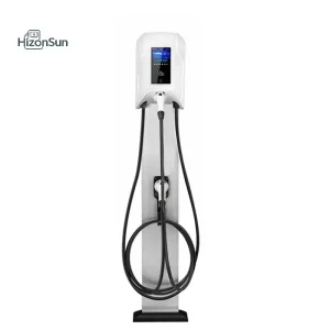
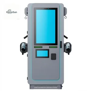
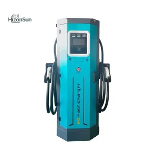
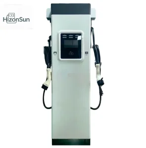
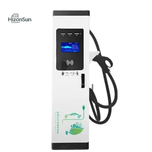
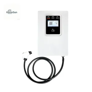
The Engineering Logic of Separated Charging Pile Architecture
As electric commercial vehicles, heavy duty e-trucks, and 800V passenger EVs flood the global transportation network, legacy "all-in-one" standalone DC fast chargers face fatal systemic limits. The separated charging pile architecture—commonly known as split-type or distributed DC fast charging systems—decouples heavy power conversion from parking bay user dispensers.
Centralized Power Rectification
Houses silicon carbide (SiC) or IGBT conversion stacks inside a weather-isolated, sound-damped utility cabinet located up to 100 meters away from vehicle bays. Minimizes noise, thermal stress, and physical footprint near parking bays.
Dynamic Power Pooling
Replaces rigid power assignments with dynamic matrix crossbar contactor routing. Automatically shifts 20kW/30kW/40kW modular power granular increments in real time, matching individual battery acceptance curves across up to 12 charging bays.
Ergonomic Ultra-Slim User Terminals
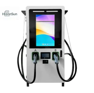
User dispensers carry zero bulky power electronics—only metering, liquid-cooled or boost-rated cable harnesses, and human-machine interface (HMI) screens. Yields compact parking footprints with ADA and CE ergonomics.
Global Enterprise Procurement: Capex, Opex & TCO Analysis
For Charge Point Operators (CPOs), fleet logistics yards, heavy transit depots, and energy conglomerates, evaluating separated charging pile infrastructure requires a total cost of ownership (TCO) methodology that balances substation capacity constraints, grid connection penalties, and operational lifecycles.
| Evaluation Parameter | Standalone Monolithic Fast Chargers (6x 120kW) | ODM Separated Charging Pile System (720kW Matrix Hub) | Commercial Impact Advantage |
|---|---|---|---|
| Grid Connection Requirement | 720 kVA static peak demand; high transformer upgrade cost | 480–600 kVA with active power pooling & peak capping | -25% to -35% Substation Capex |
| Power Asset Utilization | 22% – 38% (power trapped at idle or trickle bays) | 68% – 84% (matrix reallocation across all connected EVs) | 2.1x Throughput Revenue |
| Bay Footprint & Civics | Bulky footprint; heavy structural bollards required per bay | Ultra-compact dispensers (0.12 m² footprint); central cabinet in utility yard | Saves 40% Usable Parking Space |
| Acoustic Emission | 68–75 dBA high-noise fans near retail customers/drivers | <52 dBA at dispenser; cabinet placed behind acoustic walls | Full Urban Compliance |
| Maintenance & Downtime | Single rectifier failure halts the entire double-gun dispenser | N+1 module redundancy; modular hot-swapping in 5 minutes | 99.8% Station Availability |
| Upgradeability (800V/Megawatt) | Complete teardown and hardware scrap required | Modular swap of rectifier racks and liquid-cooled terminal cables | 10-Year Lifecycle Longevity |
Optimizing Megawatt-Scale Grid Tariffs
Industrial power tariffs severely penalize instantaneous peak demand spikes. Separated charging pile systems integrate integrated software governors that cap aggregate power draw under utility-negotiated ceilings while dynamically balancing output across vehicle queues, saving thousands in monthly demand penalties.
Decoupled Maintenance Lifecycle
Dispensers exposed to harsh weather, public tampering, and physical fender-benders contain zero sensitive high-frequency power boards. When mechanical repairs occur, the master power cabinet remains online, powering adjacent charging bays without interruption.
Specialized Applications Across Mission-Critical Verticals
Turnkey split-architecture topologies custom-engineered to overcome grid limits and high-turnover duty cycles across heavy transit, highway corridors, port logistics, and commercial complexes.
Municipal Bus & Transit Depots
Overnight trickle-fast charging for 40 to 100 electric buses. A centralized 480kW–720kW split power matrix dispenses low, continuous 40kW power to dozens of parked vehicles simultaneously, switching to high-power 300kW boost top-ups during short driver layovers.
Heavy-Duty Logistics & Port Hubs
Class 8 commercial electric semi-trucks demand high energy throughput. Our split architecture powers dual-liquid-cooled dispensers supporting continuous 500A–600A output, delivering 300km of driving range within a mandatory 30-minute cargo transshipment window.
Highway Supercharging Plazas
Interstate rest stops face extreme utilization variance—from idle mid-day hours to massive weekend holiday queues. Separated charging pile systems allow dynamic pooling where single 800V vehicles draw maximum 360kW-480kW power while adjacent cars share remaining rectifiers.
Technical Roadmap: From SiC Rectification to Megawatt Matrix Routing
Suzhou HizonSun Tech Co., Ltd. continuously invests over 12% of annual turnover into power electronics R&D. Below is our engineering roadmap for high-power conversion topologies, thermal dissipation systems, and cloud connectivity.
- Transition from silicon IGBTs to Silicon Carbide (SiC) MOSFET rectifiers.
- Ultra-wide output range: 150VDC to 1000VDC constant full-power output.
- Standby parasitic power consumption reduced below 0.1% through auto-sleep.
- High efficiency exceeding 96.5% at nominal load, lowering site cooling costs.
- Full liquid cooling integration for both power rectifier stacks and dispenser cables.
- Acoustic envelope constrained under 48 dBA for luxury urban installations.
- Bi-directional AFE (Active Front End) enabling V2G (Vehicle-to-Grid) frequency stabilization.
- Dynamic relay crossbar matrices reassigning module power in 100ms switching cycles.
- Megawatt Charging System (MCS) integration exceeding 1.2MW single-port throughput.
- Direct MV (Medium Voltage) AC grid connection (10kV/20kV) bypassing step-down transformers.
- Integrated DC bus routing directly linking BESS (Battery Storage) and rooftop solar.
- AI-driven autonomous power forecasting based on vehicle telematics and grid spot pricing.
Global Compliance & Localization Support
Entering regulated utility jurisdictions requires extensive documentation, certified laboratory testing, and protocol interoperability. Our dedicated international engineering teams provide customized hardware and firmware certification packaging across Tier-1 markets.
European AFIR & MID
Full compliance with the Alternative Fuels Infrastructure Regulation (AFIR), integrated German Eichrecht-ready MID certified DC energy meters, transparent ad-hoc credit card POS terminals, and CCS2 standard interoperability.
North American UL & NEVI
Built to UL 2202 and UL 2594 safety standards with CTEP certification for public billing accuracy. Native hardware options for dual CCS1 and native Tesla/NACS (SAE J3400) connectors with 50-state utility approvals.
ISO 15118 & OCPP 2.0.1
Support for ISO 15118-2/20 Plug & Charge with automated TLS cryptographic certificate exchanges. Fully compliant with OCPP 1.6J and OCPP 2.0.1 for connection to major European and American enterprise cloud networks.
Harsh Climate Protection
Standard IP54/IP55 industrial protection, C5M anti-corrosion marine-grade exterior powder coating, and specialized internal dehumidification heating circuits for sub-zero Nordic or humid tropical coastal environments.
Separated Architecture Engineering Matrix
Detailed technical specifications across our flagship split-type power master cabinets and user dispensers for global project tenders.
| Technical Metric | HZS-360-SP (360kW Master) | HZS-480-SP (480kW Master) | HZS-720-SP (720kW Master) | UD-Series User Dispenser |
|---|---|---|---|---|
| Input Grid Voltage | 3-Phase 380V/400V/480V ±15% | 3-Phase 380V/400V/480V ±15% | 3-Phase 380V/400V/480V ±15% | Supplied via DC Master Bus |
| Output Voltage Range | 150VDC – 1000VDC wide range | 150VDC – 1000VDC wide range | 150VDC – 1000VDC wide range | 150VDC – 1000VDC |
| Power Granularity | 30kW / 40kW Modular Steps | 30kW / 40kW Modular Steps | 30kW / 40kW Modular Steps | Dynamic Matrix Allocated |
| Maximum Dispensers | Up to 4 Dual-Gun Satellites (8) | Up to 6 Dual-Gun Satellites (12) | Up to 6 Dual-Gun Satellites (12) | Single or Dual CCS2/CCS1/NACS |
| Maximum Current | Up to 500A (liquid-cooled ready) | Up to 600A continuous boost | Up to 800A aggregate matrix | 250A (Air) / 500A (Liquid) |
| Enclosure Protection | IP54 Outdoor / IK10 impact | IP54 Outdoor / IK10 impact | IP54 Outdoor / IK10 impact | IP55 Outdoor / IK10 impact |
| Noise Emission | <65 dBA (acoustic baffles) | <68 dBA (acoustic baffles) | <70 dBA (variable fan speed) | <50 dBA ultra-silent at bay |
| HMI & Payment Options | Service LCD Internal Debug Panel | Service LCD Internal Debug Panel | Service LCD Internal Debug Panel | 10.1" / 15.6" Sunlight LCD + POS |
Frequently Asked Questions by Technical Procurement Teams
Direct technical answers addressing power matrixing, cabling distances, reliability, and customization options from our chief hardware engineers.
What is the maximum permissible distance between the power cabinet and charging dispensers?
How does the dynamic matrix power allocation perform when multiple EVs arrive simultaneously?
Can a 480kW or 720kW master cabinet support liquid-cooled dispensers?
What level of white-label ODM customization does HizonSun provide for CPO branding?
How does the system ensure resilience against individual power module failures?
Turnkey Charging Hardware Ready for Global Export
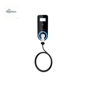
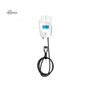
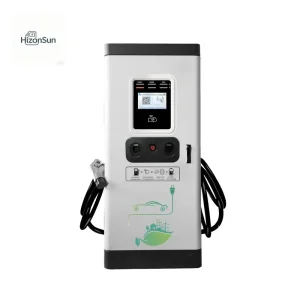
Explore additional high-capacity AC, DC, and multimedia integrated charging piles available for private labeling, OEM manufacturing, and utility integration.
Vertically Integrated Manufacturing in Kunshan, China
Operating from our 10,000 m² state-of-the-art intelligent manufacturing facility, Suzhou HizonSun Tech Co., Ltd. controls the complete production lifecycle—from SMT surface mounting and sheet-metal stamping to environmental burn-in stress testing and full-load grid simulation.
Rigorous Automated QC Protocols
Every separated charging master cabinet and user dispenser undergoes rigorous 48-hour continuous full-load burn-in testing under elevated temperature and humidity conditions. High-voltage insulation dielectric tests, surge withstand verification, and CAN protocol error-injection testing guarantee zero field defects.
Over 50 Proprietary Patents
Backed by ISO 9001, CE, CB, UL, and CQC accreditations, our engineering patents cover core innovations in dynamic matrix power switching, thermal fluid loop balancing for split dispensers, high-frequency resonance dampening, and multi-tenant smart cloud billing security.
End-to-End Supply Chain Traceability
We maintain direct strategic component partnerships with Tier-1 power electronics suppliers (Infineon, Wolfspeed, Phoenix Contact, Schneider Electric, LEM). Every sub-component is tracked via digital MES barcodes, ensuring 10-year spare-part availability and rapid warranty support.