High-Power Turnkey EV Charging Hardware Portfolio
Engineered for global CPOs, fleet operators, and industrial partners. Compliant with IEC, SAE, ISO 15118, and GB/T standards with full dynamic balancing capabilities.
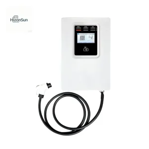
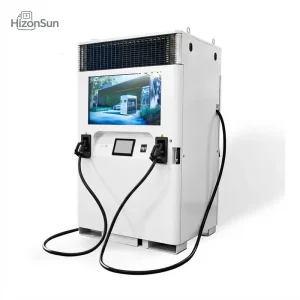
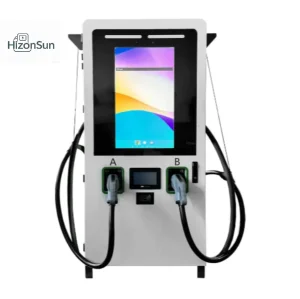
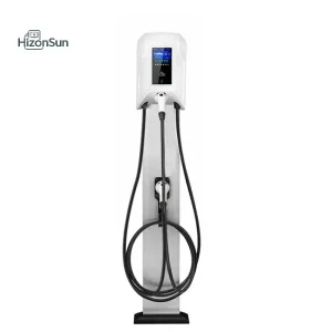
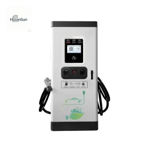
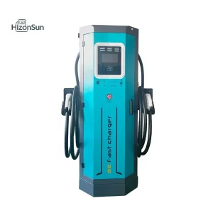
Electric Vehicle Charger Levels: Global Engineering Categorization
Understanding the electrical architecture, grid impact, and conversion topology of EV charging levels is critical for enterprise supply chain planners and infrastructure engineers.
| Charging Level | Electrical Input | Conversion Location | Power Range | Typical Connectors | Industrial Application |
|---|---|---|---|---|---|
| Level 1 (AC) | 120V / 230V 1-Phase | On-Board Charger (OBC) | 1.2 kW – 2.4 kW | NEMA 5-15, Schuko | Residential / Emergency |
| Level 2 (AC) | 208V / 240V / 400V 1-3 Phase | On-Board Charger (OBC) | 7.0 kW – 44.0 kW | Type 1 (J1772), Type 2 (Mennekes), GB/T | Commercial, Hotel, Workplace |
| Level 3 DC Fast (DCFC) | 380V – 480V 3-Phase AC | Off-Board Rectifier Subsystem | 30 kW – 180 kW | CCS1, CCS2, CHAdeMO, GB/T, NACS | Public Hubs, Urban Corridors |
| Level 4 Ultra-Fast (HPC) | 400V – 800V AC / Grid Substation | Split-Cabinet Liquid-Cooled SiC | 240 kW – 600 kW | CCS2 Liquid-Cooled, NACS (SAE J3400) | Highway Rest Areas, Heavy Transit |
| Megawatt Charging (MCS) | Medium Voltage (MV) Direct Feed | Centralized Solid-State Transformer | 1.0 MW – 3.75 MW | MCS Standard Connector | Class 8 Freight, Ferries, Mining |
Level 2 Smart AC Infrastructure
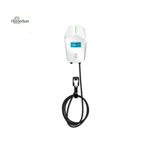
Level 2 charging remains the workhorse of destination and long-dwell environments. Operating predominantly at 230V single-phase or 400V three-phase, these systems avoid massive utility transformer upgrades while providing 11kW to 44kW outputs.
- Onboard EV conversion utilizing the vehicle's internal rectifier.
- ISO 15118-ready hardware for Plug & Charge and automated billing.
- Dynamic Load Balancing (DLM) cascading across 30+ units on shared feeders.
Integrated & Split DC Fast Topologies
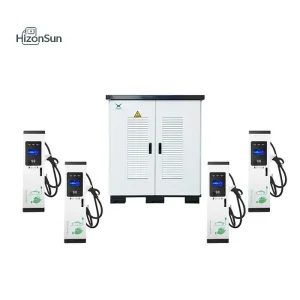
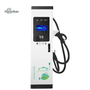
DC Fast Chargers bypass the limitations of onboard rectifiers by delivering conditioned high-voltage DC directly to the traction battery pack. Modern OEM architectures leverage high-frequency resonant power conversion modules.
- Constant-power module voltage ranges: 150V DC to 1000V DC.
- Silicon Carbide (SiC) MOSFET semiconductors reducing thermal losses by 35%.
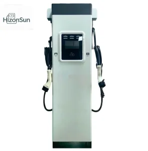
- Dual-gun dynamic matrix switching matching multi-vehicle battery demand.
Microgrid & Solar ESS Integration
Grid connection limitations in remote locations or constrained urban centers make direct megawatt utility interconnections cost-prohibitive. Energy Storage System (ESS) integrated DC chargers decouple grid pull from charging bursts.
- Integrated 100kWh–200kWh Lithium Iron Phosphate (LFP) buffers.
- Peak-shaving operation modes reducing monthly utility maximum demand charges.
- Bi-directional active front-ends ready for Vehicle-to-Grid (V2G) operation.
Global Market Reality: Supply Bottlenecks & Factory Capabilities
The global EVSE hardware sector has shifted from cottage-scale assembly to automotive-grade mass manufacturing. CPOs face strict reliability targets, demanding lower Total Cost of Ownership (TCO) and certified MTBF performance.
Tier-1 Manufacturing Bottlenecks & Resolution
Charge point uptime failures historically stemmed from substandard thermal routing, poor potting of sensitive electronic assemblies, and firmware desynchronization with evolving vehicle Battery Management Systems (BMS). High-uptime facilities address these points with stringent manufacturing controls:
- Automated SMT & Conformal Coating: Protection against humidity, saline air, and airborne particulate degradation (IP55 to IP65 ratings).
- Thermal Wind-Tunnel Testing: Full-cabinet heat load dissipation testing at ambient temperatures up to 55°C without current derating.
- Independent Power Matrix Switching: Granular power routing across connectors preventing complete charger outage when a single module trips.
Standardization, Compliance & Multi-Protocol Testing
Global operators face fragmented regional charging topologies. A robust OEM partner must engineer cabinets to adapt across standards without chassis re-tooling:
- Dual-Standard Integration: Hybrid designs housing both CCS2 and CHAdeMO, or CCS1 and SAE J3400 (NACS) within identical enclosure stampings.
- EMC Class B Compliance: Safe operation in urban, residential, and light commercial environments without causing radio frequency interference.
- OCPP 1.6J & OCPP 2.0.1 Ready: Native firmware compliance enabling smooth integration with global Charge Point Management Software (CPMS).
Localized Engineering Use Cases & Custom OEM Blueprints
Every commercial application presents distinct duty cycles, dwell times, and utility grid constraints. Tailoring the charging level configuration to site physics is essential for economic viability.
Public Highway Corridors
Deployment: 180kW–360kW Dual-Gun DC & Split HPC systems with liquid-cooled cables.
High-turnaround locations require maximum peak power delivery across both 400V passenger sedans and modern 800V platform vehicles. Integrated POS terminal support and credit-card readers eliminate app dependencies for transient drivers.
Retail, Real Estate & Hospitality
Deployment: 22kW–44kW AC Chargers & 30kW–60kW Compact Wallbox/Floor DC Chargers.
Targeting 45-minute to 3-hour dwell profiles. Optional integrated 32-inch high-brightness digital advertising displays convert charging stalls into self-funding media assets while providing revenue-grade kilowatt-hour metering.
Bus Depots & Logistics Fleets
Deployment: 360kW–720kW Split-Type DC Systems with Overhead Pantographs or Remote Dispensers.
Centralized power cabinets located up to 100 meters away supply low-footprint satellite dispensers. Scheduled overnight charging utilizes Dynamic Energy Management to recharge whole fleets during the lowest off-peak tariff windows.
Technology Roadmap: The Next Decade in Power Conversion (2025–2035)
The transition from silicon to wide-bandgap semiconductors, bidirectional grid services, and autonomous vehicle charging interfaces is reshaping industrial product design.
GaN & High-Frequency SiC Topologies
Next-generation rectifiers operate at switching frequencies exceeding 100kHz, allowing a 40% reduction in magnetics footprint and passive component volume. This unlocks ultra-dense DC fast charging wallboxes suitable for standard mechanical rooms.
Bidirectional V2G & V2X Stabilization
Under ISO 15118-20, charging piles evolve from passive loads into active grid buffers. Fleet chargers supply reactive power correction and frequency response services back to distribution network service providers (DNSPs), creating new operational revenue.
Automated Robotic & Inductive Conduction
Autonomous truck fleets and robotaxis require unattended physical charging coupling. OEM factories are embedding motorized automated alignment couplers and multi-kilowatt dynamic inductive transfer coils designed to operate without human intervention.
Frequently Asked Questions: Global Industrial Procurement
Key technical answers regarding manufacturing lead times, compliance validation, and architectural scalability for global sourcing teams.
How do factory-level power matrix architectures optimize DC fast charger TCO?
What specific certifications are required for exporting chargers from China to Europe and the Americas?
How do liquid-cooled charging cables differ from air-cooled cables in Level 4 ultra-fast applications?
Can OEM manufacturers customize firmware for proprietary CPMS backends and custom protocols?
What harmonic mitigation measures are taken in high-power DC charging installations?
High-Power Commercial & Fleet Fast-Charging Solutions
Discover our extended line of advertising fast chargers, modular split systems, and specialized multi-standard EV charging systems.