
Featured Smart EV Charging Hardware Architecture
Examine our certified production series spanning Level-2 commercial AC wallboxes, high-throughput dual-gun DC superchargers, and multimedia interactive fast-charging systems engineered for Tier-1 operators worldwide.
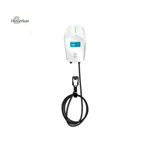
OEM AC EV Charger from China Suppliers | 3.5KW-22KW Wallbox & Floor Mounted Charging Station
Explore Specifications
OEM CE Certified China 60-360KW DC Charging Pile | EU Standard Fast Charger from Reliable Suppliers
Explore Specifications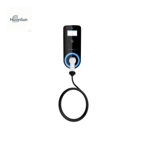
OEM China EV-ONE AC EV Charger 3.5KW-22KW | Wallbox & Floor Mounted | Compatible with GB/T/CCS/Tesla
Explore Specifications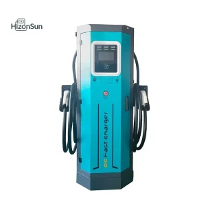
OEM 60KW-360KW Dual Gun DC EV Charger from China Factory | Octagonal Fast Charging Station
Explore Specifications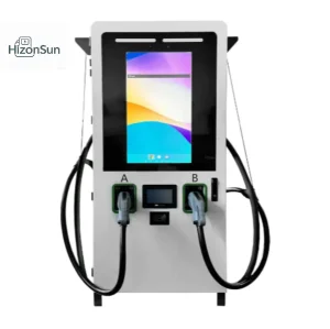
China 32-Inch Advertising DC Charging Pile: 60–240kW All-in-One Commercial Solution Supplier
Explore Specifications
ODM 32-Inch Advertising DC Charging Pile - 60-240kW All-in-One Solution by China Suppliers
Explore Specifications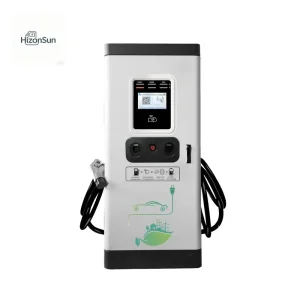
China 60KW-400KW Integrated DC EV Charging Pile | Fast Charger Solutions for Commercial Use
Explore Specifications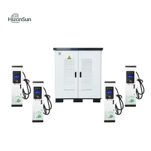
China 360KW-720KW Split Type DC Fast EV Charging Station | 8-12 Guns, GB/CE/CCS2 Compatible
Explore SpecificationsGlobal Corporate Procurement Demands in Smart EV Charger Manufacturing
Navigating capital allocation for multi-megawatt charging infrastructure demands deep alignment between electronic manufacturing services (EMS), software lifecycle engineering, and robust hardware resilience.
Turnkey Hardware & Firmware ODM
International charge point operators (CPOs) and energy conglomerates no longer accept off-the-shelf, white-label chassis. Strategic procurement requires custom PCB layouts, proprietary embedded Linux/FreeRTOS core firmware stacks, and deep mechanical adaptations suited for brand-specific design languages.
Interoperability & Protocol Stacks
Seamless interoperability is the defining risk variable for fleet electrification and public hubs. Tier-1 enterprise RFPs necessitate native OCPP 1.6J/2.0.1 compliance, ISO 15118-2/-20 implementation for automated Plug & Charge (PnC), and multi-gateway backend communications.
Total Cost of Ownership & MTBF
Industrial purchasers calculate ROI based on uptime guarantees exceeding 99.2%. Factory engineering must guarantee a high Mean Time Between Failures (MTBF > 120,000 hours), isolated air ducts for power modules, and hot-swappable subassemblies to minimize on-site maintenance cycles.
Macro Industry Solutions for Modern Electrification
Deploying high-power charging at scale requires balancing dynamic grid limitations, fluctuating electricity tariffs, and fleet turnaround times across diverse real-world operating environments.
Highway Megawatt Hubs
High-speed corridor corridors require rapid replenishment. Utilizing 360kW to 720kW split-type architectures, power matrices dynamically redirect power between liquid-cooled CCS2 dispensers, allowing passenger EVs to gain 300 km of range within 10 to 12 minutes.
Fleet Depots & Logistics
Electrified delivery vans and public bus fleets require deterministic overnight charging. Scheduled multi-gun charging algorithms balance high-volume load spikes, avoiding utility demand charges while ensuring vehicle readiness by scheduled departure times.
Commercial Multi-Tenant Sites
Shopping centers and office parks demand intelligent AC Level 2 (7kW–22kW) and compact DC (20kW–40kW) solutions. Dynamic Load Balancing (DLB) dynamically gauges entire facility draw, safely delivering leftover building capacity to charging patrons.
Microgrid Solar-Storage Piles
In areas with weak grid capacity or prohibitive interconnection fees, 100kWh/200kWh battery-buffered charging stations bridge the gap. Integrated LFP batteries absorb solar PV generation and off-peak utility power to discharge fast DC bursts when vehicles dock.
Engineering Roadmap: Silicon-Carbide, V2G & High-Voltage Topologies
The transition from legacy 400V battery architectures to 800V/1000V silicon carbide (SiC) platforms is redefining EVSE manufacturing. The table below details our technological benchmarks across core power domains.
| Architecture Subsystem | Legacy Technology Baseline | Current Production Generation | Next-Generation (2026–2028 Horizon) |
|---|---|---|---|
| Power Semiconductor Core | Silicon IGBT switching modules (92%–94% efficiency) | Silicon Carbide (SiC) MOSFETs (95.5%–96.5% efficiency) | Gallium Nitride (GaN) / Gen-3 SiC hybrid matrix (>97.8% peak efficiency) |
| DC Operating Voltage Band | 150V – 500V nominal output range | 200V – 1000V wide continuous output range | Up to 1250V ultra-wide voltage band for heavy commercial transport (MCS) |
| Bidirectional Grid Dynamics | Unidirectional power flow (G2V only) | V2G / V2H hardware-ready with ISO 15118-20 support | Full BPS active bi-directional virtual power plant (VPP) microgrid coordination |
| Thermal Dissipation Scheme | Forced-air cooling through internal components | Independent isolated air ducts + potted modules | Full immersion & closed-loop liquid cooling at the dispenser & rectifier level |
| Connector & Cable Dynamics | Air-cooled CCS1/CCS2 up to 200A continuous | Air-cooled 250A / Liquid-cooled 500A continuous | Liquid-cooled Megawatt Charging System (MCS) rated up to 1500A continuous |
From Concept to Mass Production: The 5-Stage ODM Workflow
Transforming technical specifications into certified field deployments demands precision engineering checkpoints across each milestone.
Specification & Feasibility
Thermal profiling, mechanical styling renderings, regional electrical code review (UL vs CE vs GB), and bill-of-materials (BOM) cost target alignment.
Engineering EVT Phase
Rapid functional prototyping, structural sheet metal laser cutting, custom PCBA layout routing, and foundational firmware integration.
Design Validation (DVT)
Environmental stress testing (-30°C to +55°C), EMC/EMI chamber validation, full-load thermal imaging, and destructive safety testing.
Regulatory Compliance
Third-party lab audits with TÜV Rheinland, SGS, or UL to finalize CE, CB, UL, and FCC marks alongside OCPP protocol certification.
Mass Production (PVT)
Automated inline SMT assembly, robotic potting, 100% full-load burn-in testing, serialization, and secure palletized export packaging.
Global Compliance Verification & Localized Support Networks
Deploying high-voltage infrastructure across jurisdictions requires unwavering adherence to international safety directives and dedicated technical assistance.
Multi-Jurisdictional Certification
Our products undergo stringent audits to satisfy regional regulatory frameworks: CE-EMC and CE-LVD under EN IEC 61851-1/-23 in Europe; UL 2594 and UL 2202 in North America; and comprehensive CQC and CB safety schemes covering Asia and South America.
36 Global Support Centers
Hardware longevity is guaranteed through localized field application engineering (FAE) hubs located across Europe, North America, Southeast Asia, and South America. Local engineering teams handle level-2 diagnostics, warranty parts swap-outs, and grid commissioning.
Traceability & ISO 9001 Controls
Every subassembly carries a laser-etched 2D data-matrix identifier tied directly to our enterprise MES. From automated SMT paste inspection (SPI) and X-ray soldering audits to multi-hour high-temperature chamber burn-in, component lifecycles remain completely traceable.
Frequently Asked Questions by Procurement & Engineering Teams
Detailed technical, contractual, and regulatory clarifications addressing key considerations in global EVSE procurement.
What is the typical lead time and NRE investment structure for an ODM custom charger project?
A standard turnkey ODM development cycle requires 10 to 14 weeks from sign-off of initial industrial design (ID) and engineering specifications to delivery of first engineering validation test (EVT) working samples. Mass production tooling cycles (including injection molds for plastic bezels and progressive dies for sheet-metal enclosures) typically take an additional 4 to 6 weeks. Non-Recurring Engineering (NRE) fees depend on enclosure customization and proprietary PCBA integration, and are structured with full rebates once contracted purchase milestones are achieved.
How does your factory handle backend integration and cybersecurity for OCPP 2.0.1 and ISO 15118?
All smart chargers are equipped with hardware-based cryptographic secure elements (e.g., ATECC608 or equivalent HSM modules) to handle secure key storage, root-of-trust authentication, and cryptographic certificate storage required by ISO 15118 Plug & Charge. Our embedded firmware supports OCPP 1.6-JSON, OCPP 2.0.1, and OpenADR 2.0b via secure TLS 1.3 tunnels. We provide API sandboxes and assist your cloud engineering team with end-to-end integration testing before factory gate rollout.
What thermal management techniques are used in your high-power DC fast charging cabinets?
Our 60kW through 360kW integrated DC charging stations utilize an isolated independent air-duct architecture. The internal power conversion modules are sealed in potted enclosures that separate critical electronic components from ambient moisture, particulate matter, and salt fog. For 360kW to 720kW supercharging dispensers delivering 500A continuous currents, we integrate closed-loop liquid-cooling circuits with dedicated ethylene-glycol heat exchangers, ensuring charging cable handles remain lightweight and stay below the 85°C touch safety thresholds mandated by IEC 61851-23.
Can your charging stations support grid-constrained sites without costly utility upgrades?
Yes. We address localized grid bottlenecks via two primary engineering methods: software-driven Dynamic Load Balancing (DLB) and hardware-level Energy Storage System (ESS) integration. Our smart charging controllers modulate station output based on real-time external Modbus/TCP or CT meter inputs. For sites with severe electrical limitations, our 100kWh and 200kWh battery-integrated DC charging piles act as a power buffer, trickle-charging from the existing grid and discharging at up to 240kW during fast-charging sessions.
Commercial, Fleet & Storage-Integrated Product Solutions
Explore our expanded commercial hardware line, including battery-buffered microgrid stations, multi-standard AC pedestals, and modular DC fast-charging systems designed for global enterprise deployment.

ODM China Suppliers Factory Integrated Charging Pile with 100KWh & 200KWh Energy Storage for EV Charging and Solar ESS
Explore Specifications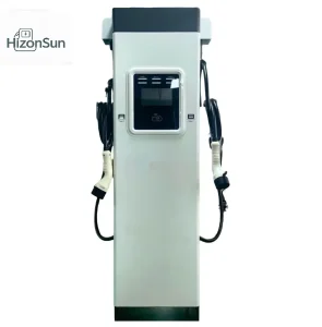
ODM 22-44KW AC Charging Station Customizable for China Standards - Reliable Factory Suppliers
Explore Specifications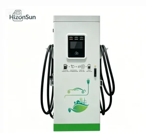
China 40KW-180KW Integrated Floor-Mounted DC EV Charger | Dual Gun | GB/IEC/UL Factories
Explore Specifications
China China Suppliers Factory Offering 100KWh & 200KWh Energy Storage Integrated Charging Pile for Solar ESS & EV Charging
Explore Specifications
China China Suppliers Factory 360KW-720KW Split Type DC Fast EV Charging Station | Intelligent Charger with 8-12 Guns
Explore Specifications
ODM EV-ONE AC EV Charger 3.5KW-22KW - China Suppliers' Reliable Factory Charging Station for Electric Vehicles
Explore Specifications
ODM 32-Inch Advertising DC Charging Pile: 60–240kW All-in-One Commercial Solution by China Suppliers
Explore Specifications